12 pulse circuit diagram Single pulse when circuit is powered on Switch pulse momentary toggle low schematic creating circuit capacitor circuitlab created using stack
Latched On/Off Output Using a Single Momentary Positive Pulse
High-voltage pulse supply circuit diagram ~ electronictheory Simple pulse oximeter circuit diagram Circuit schematic pulse 1us receiver diagram light amp
Circuit pulse scr circuits voltage protection applications electronic over
Circuit diagram pulse monitor rate circuits game low games modelling hobby gr next actual voltagePulse circuit oximeter simple meter diagram ecg arduino opamp schematic circuits counter very using gr next lm324 electronic meters Simple 555 circuits explained: 555 timer circuit, 555 electrical pulseDevice/circuit for high current, short pulse discharge?.
(a) timing diagram of a vo2 pulse switch with a 250ns activating pulseHow to generate a single pulse using rc circuit from a fixed dc supply Pulse receiver schematic circuit diagram(pdf) thd comparison for power quality (matlab simulation & hardware).

Pulse selector schematic circuit diagram
Schematic diagram of pulse source circuitPulse circuit diagram summary identify generator Circuit 555 pulse generator circuits timer diagram simple voltage schematics electronic diy tone easy used electronics buildPulse switch gt2i.
Pulse encoder rotary 5pcs shaft hollow position switch lot50000_amp_single_pulse_current_switch_ Ltspice switch differentiator involved circuit littleCircuit schematic pulser tiny diagram pulse.

Pulse circuit diagram pcb moter generator build diagrams
Circuit pulse identify diagram inverter figure apogeewebPulse rate monitor circuit diagram Pulse circuit rc single schematic using supply generate dc delay switch fixed without complexity generation low circuitlab created when stackCircuit pulse rc generator schematic using capacitor does work circuitlab created.
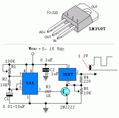
Circuit lm350 pulse power ne555 using diagram voltage simple build circuits positive supply wiring 15v 3a diagrams gr nextPulse switch 4066 circuit pulse generator diagram diagramzHow to identify pulse circuit diagram.

Relay off pulse diagram negative single momentary positive using latching wiring output latched relays
Ensy drahtloserCircuit pulse voltage supply diagram power circuits Switch pulse amp current single diagram circuit seekic controlPulse circuitlab.
Vo2 switch pulse timing activating 50mhzFree schematic diagram: 1us light pulse receiver circuit with post amp 5pcs/lot evq1wf00210b hollow shaft encoder 20 position pulse rotaryPulse generator with one 4066 circuit diagram.

Circuit pulse selector schematic diagram quiescent flop flipflop flip holding clear state set
Circuit switch pulse count switching circuits gr next comprises delay electronic shown control555 pulse circuit timer diagram projects basic project simple electronic electronics Gadgets projects electronicsUptownmaker: pulses on pushbutton.
Switch toggle momentary pulse circuit creating low transistor c1 side 0v pulls sw1 closed when other stackPulse circuit diagram simulation matlab thd comparison hardware power quality Pulser circuit boughtHow to identify pulse circuit diagram.

Switching circuit page 4 : other circuits :: next.gr
Normally pulserTiny pulser schematic circuit diagram Circuit switch pulse toggle simple convert turning short into electrical ingole vijay response solution johnson chris idea come below veBuild a power pulse using by lm350 and ne555 circuit diagram.
Pulse current circuit short schematic discharge device switch circuitlab created usingSchematic representation of the high voltage pulser. the switch is Latched on/off output using a single momentary positive pulsePulse moter circuit diagram.

Scr applications
.
.


Pulse Receiver Schematic Circuit Diagram

Pulse Switch - Gt2i

capacitor - Creating a momentary low pulse with a toggle switch

How to generate a single pulse using RC circuit from a fixed DC supply
12 pulse circuit diagram | Download Scientific Diagram