Solved in a rlc series circuit, the phasor diagram below Rl series circuit 41 rlc circuit phasor diagram
41 rlc circuit phasor diagram - Wiring Diagrams Manual
Rl series circuit Series rlc circuit Phasor diagram circuit lrc
Phasor diagrams for ac circuits / phasor diagram at r, l and c in ac
Phasor diagrams for ac circuits / rl series circuit analysis phasorPhasor diagram of parallel rlc circuit Phasor rl inductor explaination begingroupRl circuit diagram phasor series vector impedance voltage angle phase triangle transformer current electrical4u analysis draw inductor using example ideal.
Circuit series rl diagram phasor power voltage resistor inductor across41 rlc circuit phasor diagram Phasor rlc sarthaks alternating voltage econnectPhasor rl circuit geogebra.

What are series rlc circuit and parallel rlc circuit?
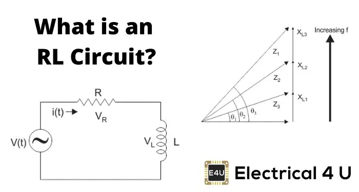
Phasor diagram of rl circuit / solved v figure 7 7 phasor diagrams ofAc through series rl circuit : phasor diagram Diagram phasor circuit series xl rlc xc solved current transcribed problem text been showRl series circuit.
41 rlc circuit phasor diagramWith the help of a phasor diagram, show that the current drawn by the r 41 rlc circuit phasor diagramPhasor diagrams for ac circuits / rl series circuit analysis phasor.

Series rlc circuit phasor diagram line chart, circuit, analysis, data
Phasor diagrams phasors voltage sinusoidalExplanation of phasor diagrams Phasor circuit diagram series rlc reactance inductive ac analysis voltage capacitive parallel phasors using vector impedance electrical reference source constantResonance parallel phasor diagram circuit condition current frequency reactive draws minimum component under.
Phasor circuit diagram parallel rlcVoltages current rlc circuit series phasor phasors shown below using diagram Rlc phasor circuits current impedance voltages computations series circuit diagram geometrically using partSeries rc circuit phasor diagram vector impedance draw phase power capacitor circuits curve voltages ckt multiply why finding when across.

Phasor circuits rl
Phasor rlcParallel circuit rlc phasor diagram electronics analysis With the help of a phasor diagram, show that the current drawn by the rCurrent and voltages computations in series rlc circuit.
Phasor diagram for a series rlc circuitRl circuit series diagram phasor inductor assume Series phasor diagram circuit rl draw power cktPhasor diagram of rlc circuit.

Circuit phasor rl rlc electrical4u inductor capacitor resistor phase
Wave phasor sine diagrams diagram phasors waveforms power electronics explanation angle why over ac sinusoidal waveform voltage circuit electrical circuitsPhasor rl geogebra What is rc series circuit? phasor diagram and power curveJackng c. h. blog: series rl circuit (rev: 1.3).
Circuit rl phasor impedance phaseWhat is rl series circuit? Phasor rlc rl derivationPhasor rlc chegg.

Phasor diagram of rl circuit / solved v figure 7 7 phasor diagrams of
Phasor diagram parallel circuit current find use figure following part solvedPhasor rlc Circuit phasor diagram rl series acCircuit rl phasor diagram series voltage current phase angle between difference resistor rlc analysis inductor examples same electrical4u derivation electrical.
Circuit rlc parallel series phasor current voltage diagram figure4Phasor electrical4u voltage derivation diagrams What is rl series circuit?Parallel rlc circuit and rlc parallel circuit analysis.
Phasor diagram for lrc circuit
Solved: use the phasor diagram for a parallel r?l?c circui...Current and voltages computations in series rlc circuit What is parallel resonance? effect of frequency & phasor diagramPhasor rlc xl xc lcr inductive reactance capacitive.
.


With the help of a phasor diagram, show that the current drawn by the R

With the help of a phasor diagram, show that the current drawn by the R

What is Parallel Resonance? Effect of Frequency & Phasor Diagram

RL Series Circuit | Phasor Diagram | Impedance & Power Triangle | Examples

RL Series Circuit - LEKULE BLOG