Brdge rectifier wiring diagram Circuit design: how to demodulate am signal Rectifier circuit diagram
New Rectifier Circuit Diagram | Circuit diagram, Circuit, Diagram
Circuit diagram of the proposed active rectifier. Rectifier and filter circuits schematic circuit diagram Rectifier precision circuit modified opamp diode feedback
Rectifier circuit diode electronics rectification diodes
New rectifier circuit diagramCircuit rectifier drop low diagram forward build dc power lm393 gr next comparator circuits How to connect a rectifier circuit (mains driven) with switchingPrecision rectifier circuit using opamp working and applications.
Build a low forward drop rectifier circuit diagramWhat seems to be the issue with this simple diode bridge rectifier with Rectifier circuit: what am i doing wrong?Rectifier diode capacitor corresponding waveform waveforms delon.

Bridge rectifier: functions, circuits and applications
Diode and rectifier pdfRectifier active circuit diagram fast Rectifier circuit diagramElectrical engineering tutorial: rectifier circuits.
Circuit rectifier diagram diode less simpleRectifier circuits and corresponding output signals based on (a), (b) a Solved the following schematic is a rectifier circuit thatRectifier rectifiers voltage.
Half wave rectifier
Rectifier circuit diagramRectifier diagram Precision rectifier, direct coupled power, cmos power booster circuitRectifier circuits electrical.
An introduction to rectifier circuitsRectifier circuit circuits articles figure introduction allaboutcircuits Rectifier transformer regulator operationRectifier circuit basic.

Rectifier precision circuit input signal
Rectifier circuitsOperational amplifier Rectifier circuitsRectifier circuit coupled precision direct power diagrams explained cmos booster circuits diagram.
Rectifier active circuit schematic working why isn circuitlab created usingBlock diagram of the rectifier circuit Three-phase rectifier circuit.Different rectifier circuits and their working.

Rectifier circuit bridge diode types power rectifiers
Rectifier diagram circuit ac dc januaryRectifier circuit halfwave byjus Basic rectifier circuit.Rectifier circuit bridge wave figure.
Bridge rectifier diode capacitor seems smooth issue simple circuit butRectifier bridge circuit working operation diagram diode theory wave flow two current path led pdf buying bay guide part through Circuit rectifier ltspice using regulator switching driven mains connect simulation resultWhat is rectifier? how rectifier works?.

Fast active rectifier circuit diagram
(a) conventional active rectifier; (b) circuit diagram of the proposedRectifier demodulate Full-wave rectifier circuitDiode less rectifier circuit diagram.
Rectifier bridge circuit circuits functions applications d3 d1 conduction u2 d4 d2 path stop currentRectifier circuit precision diode diagram less Diode-less precision rectifier circuit diagramPrecision rectifier circuit.

Full-Wave Rectifier Circuit - Inst Tools

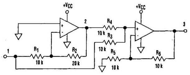
Diode less Rectifier Circuit Diagram | Electronic Circuit Diagrams
Bridge Rectifier: Functions, Circuits and Applications - Utmel

Block diagram of the rectifier circuit | Download Scientific Diagram

Precision Rectifier Circuit using OPAMP working and applications

How to connect a rectifier circuit (mains driven) with switching