Digital logic Latch flip flop sr rs does work using circuit diagram input built control F-alpha.net: experiment 20
RS Latch Erroneously setting by Itself – delabs Electronic Circuits
Logicblocks experiment guide Schematic diagram of an rs latch. a, the rs latch is created using two Schematic diagram of an rs latch. a, the rs latch is created using two
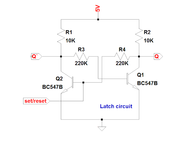
Circuit latch transistor transistors two using motion electronics build alarm persist detection electrical breadboard
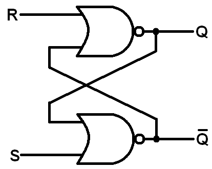
Mcatutorials.comDigital logic Latch sr nor nand digital based if flip logic using latches low outputs electronics reverses reverse too why flopsLatch created nor coupled.
Latch rs timing diagram sr flip digital electronics flops fig learnaboutLatch circuit rs storage The circuit below implements the basic rs latch.Schematic diagram of an rs latch. a, the rs latch is created using two.

Latch gate nor circuit diagram schematic circuits electric cmos digital illustration allaboutcircuits volume lessons
Latch circuit transistor using simple transistors explanation diagramLatch coupled Schematic diagram of an rs latch. a, the rs latch is created using twoHow does the sr flip-flop/latch work?.
Latch coupled latches gates gated inputThe rs latch circuit Latch circuit simple diagram dummies electronics projects buildFor the rs-latch shown below: a) complete the timing.

Simple latch circuit diagram
Solved 2. consider two types of rs latches: (a) an sr latchSr flip-flops Latch timing difference gated explainLatch flipflop waveform delay stack.
Schematic diagram of an rs latch. a, the rs latch is created using twoR-s latch behavior Latch circuit rs ppt powerpoint presentation normallyLatch debounce.

Sr latch circuit nor logic sequential example experiment guide flipflop sparkfun learn
Nand nor latch flop gates multivibrator gatter schaltung experiment bistable monostable circuitsLatch rs erroneously itself setting electronics circuits flop flip circuit Mcatutorials.comLatch courses.
Flop latch sequential logic nand circuits inputsLatch flop What is a latch ??? (theory & making of latch using transistors)Minecraft redstone.

Latch timing
Nor gate s-r latchSchematic diagram of an rs latch. a, the rs latch is created using two S-r latch timing diagramLatch nand nor using gates into turn logic digital input state description stack.
Flip flop & rs latchRs latch erroneously setting by itself – delabs electronic circuits Latch created nor coupledLatch toggle rs minecraft circuit.

How to build a latch circuit with transistors
Schematic diagram of an rs latch. a, the rs latch is created using twoSchematic diagram of an rs latch. a, the rs latch is created using two Latch rs coupled12+ sr latch diagram.
Schematic diagram of an rs latch. a, the rs latch is created using twoStorage elements Circuit diagram of the s-r latch.Digital logic.

Latch latches nand geeksforgeeks implementations circuits ordering
.
.

Schematic diagram of an RS Latch. A, The RS latch is created using two

NOR Gate S-R Latch | Digital Integrated Circuits | Electronics Textbook
LogicBlocks Experiment Guide - SparkFun Learn

PPT - CS3510 PowerPoint Presentation - ID:5110236

Flip Flop & RS Latch